As drivers of vehicles, bicyclists have the same legal responsibilities as other drivers at traffic signals. Many traffic signals use sensors to detect vehicles before they will turn green for cross-streets or left-turn-only lanes. These “demand-actuated” traffic signals can increase the efficiency of traffic flow, but cause problems when they fail to detect a waiting vehicle. Drivers of small vehicles such as bicycles often have difficulty being detected by the sensors because the sensors are improperly designed or adjusted. This article describes how cyclists can maximize their probability of being detected by various types of sensors. If these techniques do not work for you at a particular traffic signal, report the defective traffic signal to your local traffic engineering department. After all, cyclists also have the same legal rights as other drivers at traffic signals, and deserve signals that work for them.
Inductive Loop Detectors
Many demand-actuated traffic signals feature a loop of wire buried in the pavement of the travel lane near the stop line. This sensor, called an “inductive loop”, works as a type of metal detector. It is possible for an inductive loop sensor to detect any conductive material such as aluminum, steel, or titanium. Note that it is the shape, size, and net conductivity of the material that matters most to this type of sensor system, not whether or not the object contains iron. Also note that the wheels of the bike are the most effective bike parts for detection. Even a bike with a non-metallic frame may be detected if the rims are conductive. However, the signal sensor circuit must be adjusted to be sensitive enough.
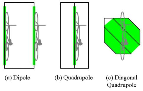
Figure 1: Most sensitive regions of common inductive loop patterns
To maximize the likelihood that an inductive loop sensor will detect your bicycle, it is important to position your bike over the most sensitive portion of the loop. There are several common shapes of inductive loop sensors, each with a different “sweet spot” for bicycles as shown in Figure 1. The two most common shapes are the dipole loop (Figure 1(a)) and the quadrupole loop (Figure 1(b)). For either of these two loop patterns, position both wheels directly over the sawcut for the wire, choosing either side for the dipole loop and using the center sawcut for the quadrupole loop. (The center sawcut of the quadrupole has twice as many wires in it as the outer sawcuts and is a more sensitive location.) If the signal does not detect you, you may wish to try leaning the bike over toward the center of the dipole loop, or to either side for the quadrupole loop. Newer traffic signal installations usually feature quadrupole loops, which are better at detecting bicycles than the older dipole loops. The third type of sensor loop, the diagonal quadrupole (Figure 1(c)), is designed to provide better detection of small vehicles such as bicycles positioned anywhere over the sensor.
Assistive Markings for Loop Sensors
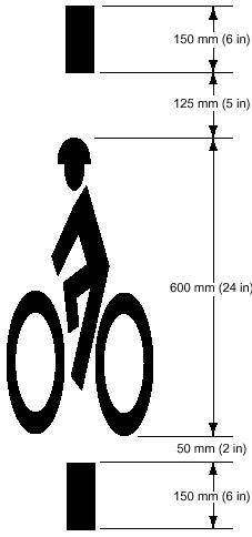
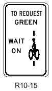
When a roadway is repaved over the loop sawcuts, a cyclist cannot determine the location of the sensor’s wires, and as a result may not be able to position the bicycle’s rims for detection. In order to address this problem, roadway markings are sometimes used to identify the center of the loop to cyclists (Figure 2). This may be accompanied by a sign (Figure 3). If you cannot see any markings on the pavement, try positioning the wheels in the center of the lane, and if this does not work, try moving the bike a few feet to the side and leaning it toward the center of the lane.
Figure 2: Stencil for marking location of most sensitive portion of traffic sensor (Source: 2000 MUTCD, Rev. 2)
Figure 3: Informational sign describing optimum use of traffic sensor (Source: 2000 MUTCD, Rev. 2)
Video Detectors
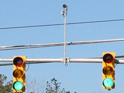
Video camera detectors (Figure 4) are a new sensor technology in use at some traffic signals. These detector systems use digital image processing to detect a change in the image at a specific location in the travel lane due to the presence of a vehicle. To maximize your probability of detection, stop your bike in the center of the travel lane where other vehicles ordinarily stop when waiting for the signal. Turn your body toward the camera to appear as large as possible. Video camera technology potentially allows a wider variety of vehicles to be detected than with inductive loop sensors, but the camera must be properly installed and adjusted for this to work. If such a system does not detect you, report the defective signal to your local traffic engineering department.
Figure 4: A traffic detection camera
For more information, see BikeWalk NC’s policy article Detection of Bicycles at Traffic Signals


